Weighing Vessels, Silos and Hoppers: Engineering for Efficient Inventory Management
30 June 2026
In the process industry, inventory accuracy is paramount. However, weighing a 50-tonne vessel or a 200 m³ storage silo under industrial conditions is not as simple as installing weight sensors and reading a display. It requires designing a complete measurement chain capable of withstanding agitator vibrations, extreme thermal variations, corrosive environments (chemical washdowns, ATEX zones) and regulatory constraints. Poor mechanical integration or poorly isolated piping can completely compromise process accuracy. So, how do you transform a massive structure into a high-precision measurement tool? This guide provides the key insights for robust weighing instrumentation, from selecting the right sensor technology to on-site commissioning.
Why Vessel Weighing Outperforms Level Measurement for Inventory Control
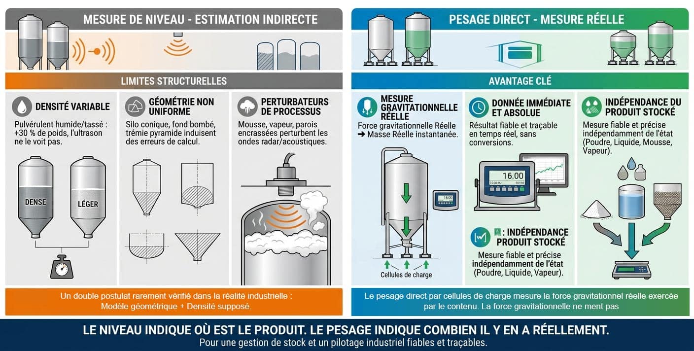
Level measurement technologies (such as radar, ultrasonic and capacitive probes) calculate the height of a product, then convert this theoretical volume into mass using a geometric model and an assumed constant density. In an industrial environment, this double assumption is a permanent source of errors.
Conversely, direct weighing using load cells is completely independent of the material's shape, state or properties. It directly measures the actual gravitational force exerted by the mass.
The Physical and Structural Limitations of Level Measurement
Density Variability: The Invisible Enemy of Volume
The bulk density of a product (especially powders or grains) constantly fluctuates depending on moisture levels, mechanical compaction at the bottom of the cone, or aeration during filling. Consequently, the same volume of stored material can weigh up to 30% more without a radar or ultrasonic sensor detecting any change at all.
Shifting Surface Profiles (The Cone Effect)
During filling or discharging phases, the material surface never remains flat. It forms a filling or emptying cone (angle of repose). Radar waves measure a specific point or a rough average, but they are incapable of calculating the exact volume of these complex, shifting geometric shapes.
Signal Interference: Foam, Vapour and Fouling
Process environments are demanding. The presence of surface foam on liquids, dense vapours, airborne dust, or product build-up on the walls (scaling/clogging) creates obstacles. These factors absorb or distort the acoustic and electromagnetic signals of level sensors.
In contrast, weighing is entirely unaffected by these factors. Whether the product is liquid, solid, foaming, compacted, or stuck to the vessel walls, a kilogram is a kilogram. The measurement is immediate, absolute, and immune to the internal environment of the vessel.
Tangible Safety and Profitability Benefits for the Plant
Implementing a direct weighing engineering solution transforms your storage infrastructure into a strategic asset.
Real-Time Supply Chain Optimization
Accurate knowledge of stock levels enables automated reorder triggers with suppliers. Consequently, overstocking costs are reduced, and production downtime due to stockouts is eliminated.
Process and Infrastructure Safety
Weighing provides foolproof protection against overfills (preventing risks of silo ruptures or explosions) and allows for the instantaneous detection of process anomalies (such as abnormally fast consumption, leaks, or material blockages).
Strict Traceability and Material Balancing
In the chemical, pharmaceutical and food industries, inventory precision is the cornerstone of recipe traceability and the exact calculation of production yields.
Expert Advice
A measurement discrepancy of just 0.5% on a 100-tonne flour silo represents 500 kg of unaccounted material per cycle. Over 250 production days, this invisible drift can lead to annual losses worth tens of thousands of pounds. Direct weighing eliminates this structural uncertainty right from the design phase.
Silos, Vessels and Hoppers: Three Containers, Three Industry Challenges
Each type of container imposes its own mechanical and environmental constraints on the measurement chain. Ignoring them exposes the system to rapid measurement drift or premature instrumentation failure.
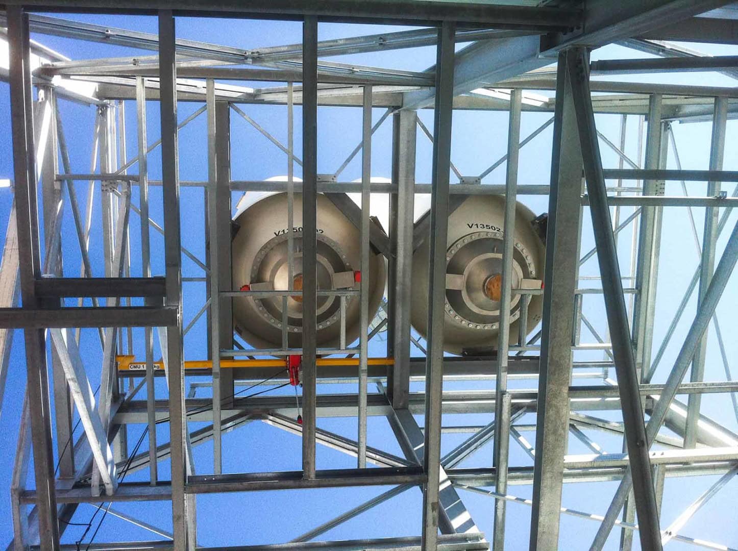
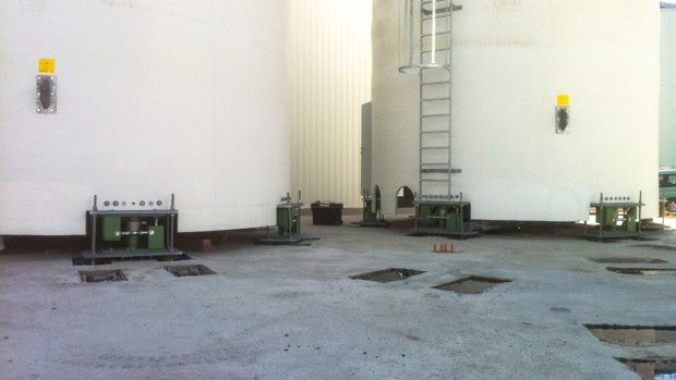
Outdoor Silos: Weather Is the Enemy
The Problem: Exposed to wind, sun, and day-to-night temperature fluctuations, an outdoor silo undergoes considerable thermal stress. The structural steel expands and contracts differently from the concrete foundation, generating horizontal movement at the silo legs.
The Risk (Structural Stress): If the support points are completely rigid, these invisible expansion forces create permanent, asymmetrical preloading on the load cells, which can totally distort the measurement. The operator will then observe seasonal zero drift, false level alarms, and erroneous material balances. This can induce an invisible calculation error of several tonnes.
The Solution: Integrating specific mounting kits equipped with a pendulum design (or a self-centring rocker pin) coupled with a mechanical anti-tilt system. These modules allow controlled horizontal freedom of movement (typically a few millimetres), enabling the silo's metallic structure to expand and contract freely. Parasitic lateral forces are completely absorbed by the kit, ensuring that only the vertical gravitational force is transmitted to the sensor's measurement axis
Outdoor silo weighing
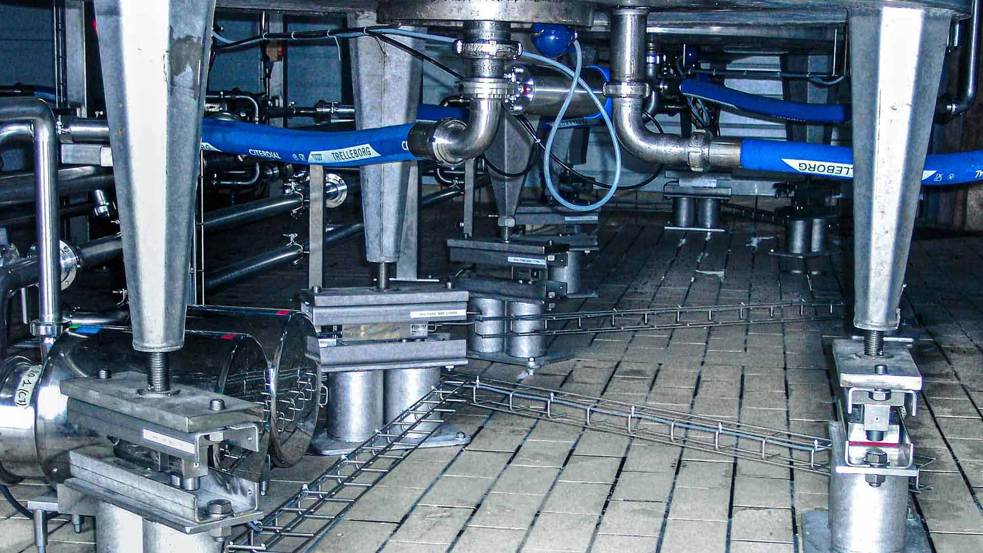
Agitated Vessels: Parasitic Forces as the Primary Adversary
The Problem: An industrial agitator or mixer generates horizontal forces, rotational torques, and continuous vibrations that are transmitted directly to the vessel structure.
The Risk (Agitation): These parasitic forces overlay the weighing signal and introduce significant dynamic errors. On screen, the weight display becomes unstable, making process control impossible and causing premature wear on the supports.
The Solution: A 3-point isostatic mounting arrangement using load cells installed in mounting kits with integrated vibration dampeners. Additionally, all piping must be isolated using horizontal flexible couplings (bellows), and advanced dynamic filtering must be applied at the weight transmitter level.
Dosing Hoppers: Precision as an Absolute Requirement
The Problem: In gravimetric dosing (loss-in-weight/gain-in-weight), the hopper operates in very fast filling and discharging cycles. The repeatability of valve openings and closings continuously strains the system.
The Risk (Agitation): Repeated shock loads and vibrations from neighbouring equipment (such as conveyors or vibrators) lead to premature fatigue of the strain gauges. After just a few months, the system exhibits chronic zero drift.
The Solution: Utilizing load cells engineered with a high safety overcapacity (150% to 300% of the nominal capacity), combined with lift-off protection (anti-uplift stops) and high-speed data acquisition electronics.
Planning the Instrumentation for a Silo or Process Vessel?
Don't let parasitic forces distort your inventory data. Discuss your mechanical constraints directly with a Captels expert today.
Compression vs Shear Beam Load Cells: The Right Tool for Every Application
Compression load cells operate under axial crushing forces. Designed to withstand massive loads (up to several hundred tonnes), they are installed directly beneath the structure's supports. They are the industry standard for high-capacity silos. While their mechanical rigidity is a key strength, they have poor tolerance for uncompensated lateral forces.
Shear beam load cells, on the other hand, measure the internal sliding stress of metal molecules against one another, known as shearing force. They offer excellent resistance to lateral forces, such as vibrations and structural thermal expansion. More compact in design, they excel on low- to medium-capacity hoppers and process vessels.
Voici la traduction de cette section cruciale sur les kits de montage, optimisée pour le SEO britannique (UK). Le vocabulaire technique a été sélectionné pour cibler les requêtes liées à la sécurité mécanique et aux accessoires de pesage indispensables (weighing modules, mounting kits, anti-uplift).
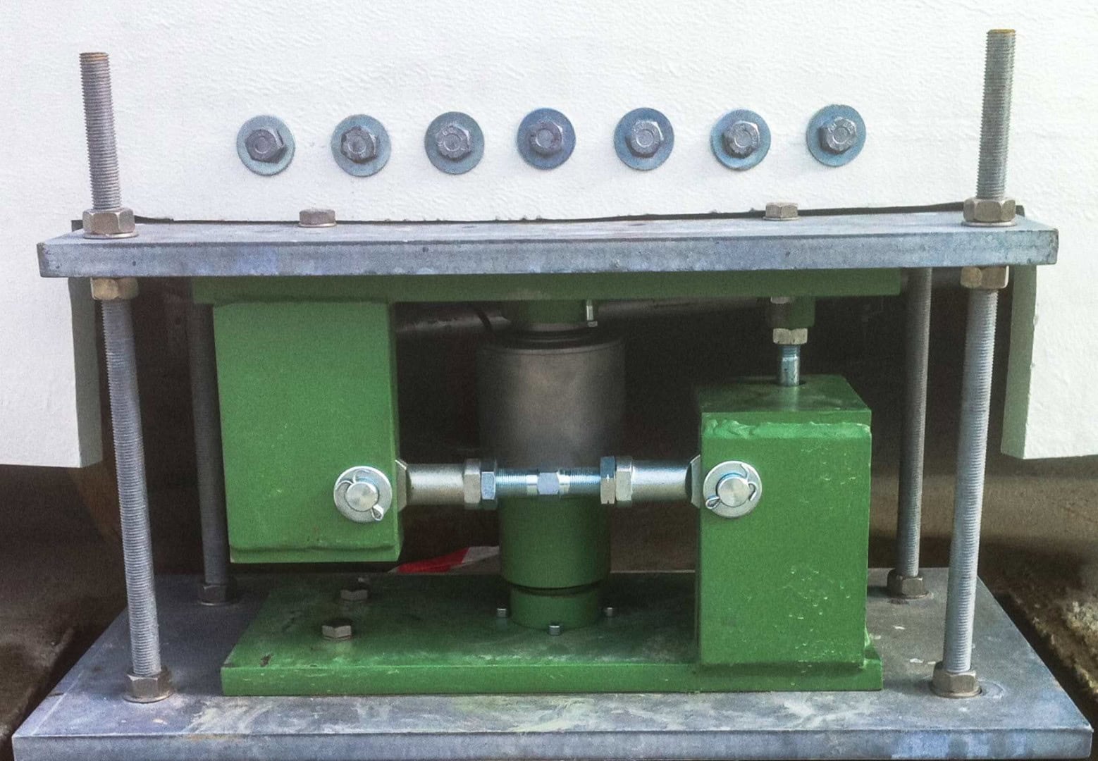
Mounting Kits: The (Too) Often Overlooked Link in the Measurement Chain
A premium load cell, even one with the highest theoretical accuracy, will never deliver its rated performance if it is installed in a weighing module that is unsuited to the application. In silo and vessel weighing, the mounting kit is not a mere accessory; it is the vital transmission component that isolates the sensor from parasitic forces.
To guarantee both measurement accuracy and structural safety, an industrial weighing kit must incorporate three critical functions:
Pendulum Design: Mastering Thermal Expansion
Temperature fluctuations and material transfers cause unavoidable structural movements. Pendulum-style assemblies (rocker mounts) allow the vessel to expand or contract freely. Parasitic radial forces are eliminated, ensuring that only the vertical force (the actual weight) is transmitted to the sensor.
Anti-Uplift Restraints: Countering Wind Loading and Vacuum Pressures
These are indispensable for outdoor silos exposed to high winds (causing overturning moments) or for process vessels subject to internal vacuum conditions. These mechanical safety devices prevent the structure from tilting or tearing away from its foundations, without binding or restricting the load cell during normal operation.
Lateral and Anti-Rotation Stops: Absorbing Dynamic Forces
During rapid discharge phases, agitator startups, or seismic events, the vessel is subjected to torsional forces and lateral shock loads. Side stops (lateral restraints) limit the horizontal displacement of the structure to protect the physical integrity of the load cell.
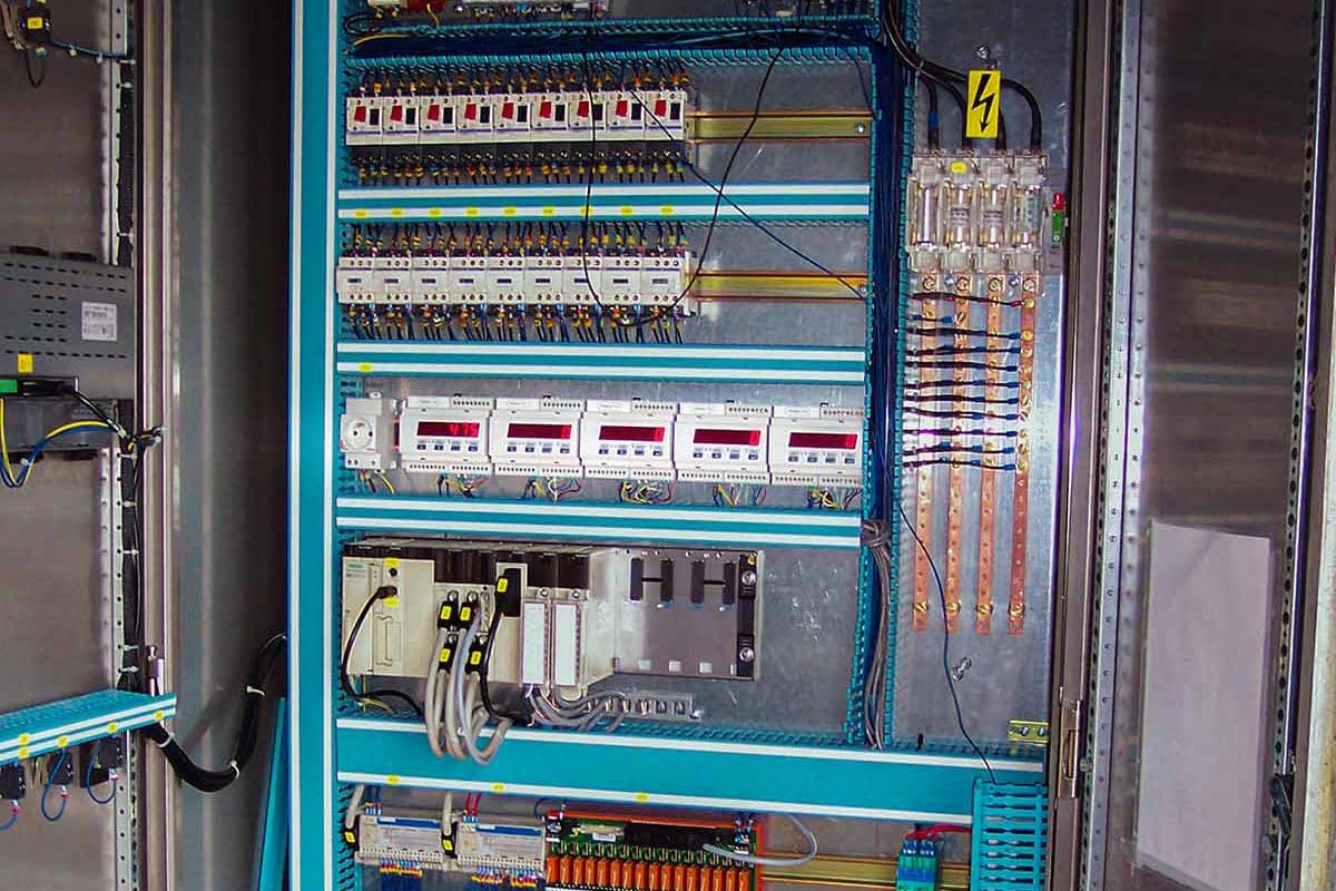
Instrumentation: From the Load Cell to the Control System
If load cells are the "muscles" of the weighing system, the instrumentation is its nervous system. The raw electrical signal emitted by a sensor (expressed in millivolts per volt, mV/V) is incredibly weak and sensitive. The choice of electronic processing components dictates the final accuracy of the measurement chain and its capacity to integrate seamlessly into your automation architecture.
A standard instrumentation chain relies on three technological pillars:
The Waterproof Junction Box: Balancing at the Source
Positioned as close as possible to the structure's support points, its role is to sum and balance the signals from the various load cells connected in parallel. Industrial models feature corner-correction circuits (potentiometers) to adjust for slight differences in sensor sensitivity, guaranteeing identical measurements regardless of how the product is distributed inside the silo. For food or chemical processing environments, a waterproof stainless-steel enclosure is essential to withstand high-pressure washdowns.
The Weighing Transmitter: The Converter Brain
Its purpose is to digitize the cumulative analogue signal and convert it into a usable mass value. Beyond simple conversion, a high-performance transmitter stands out through its sampling speed (vital for hopper dosing) and its digital filtering algorithms, which are capable of filtering out mechanical "noise" caused by motor or agitator vibrations
Industrial weighing transmitter
The Communication Interface: Choosing the Right Connectivity
Transferring weighing data to a Programmable Logic Controller (PLC) or a Supervisory Control and Data Acquisition (SCADA) system follows two distinct approaches:
The 4-20 mA Analogue Current Loop: A historical standard that remains popular due to its ease of implementation and robustness over long distances. However, it is limited to transmitting a single variable (the weight) and remains susceptible to electromagnetic interference (EMI) if cabling is not properly shielded.
Fieldbuses and Industrial Ethernet Networks (Profinet, Modbus TCP, IO-Link): These propel industrial weighing into the Industry 4.0 era. These digital protocols offer maximum resolution with zero conversion loss, but crucially, they provide advanced remote diagnostics. They enable critical alerts to be fed back for predictive maintenance, such as sensor failure, zero drift, or accidental overloading.
Decision Scenarios: Three Real-World Cases to Guide Your Choice
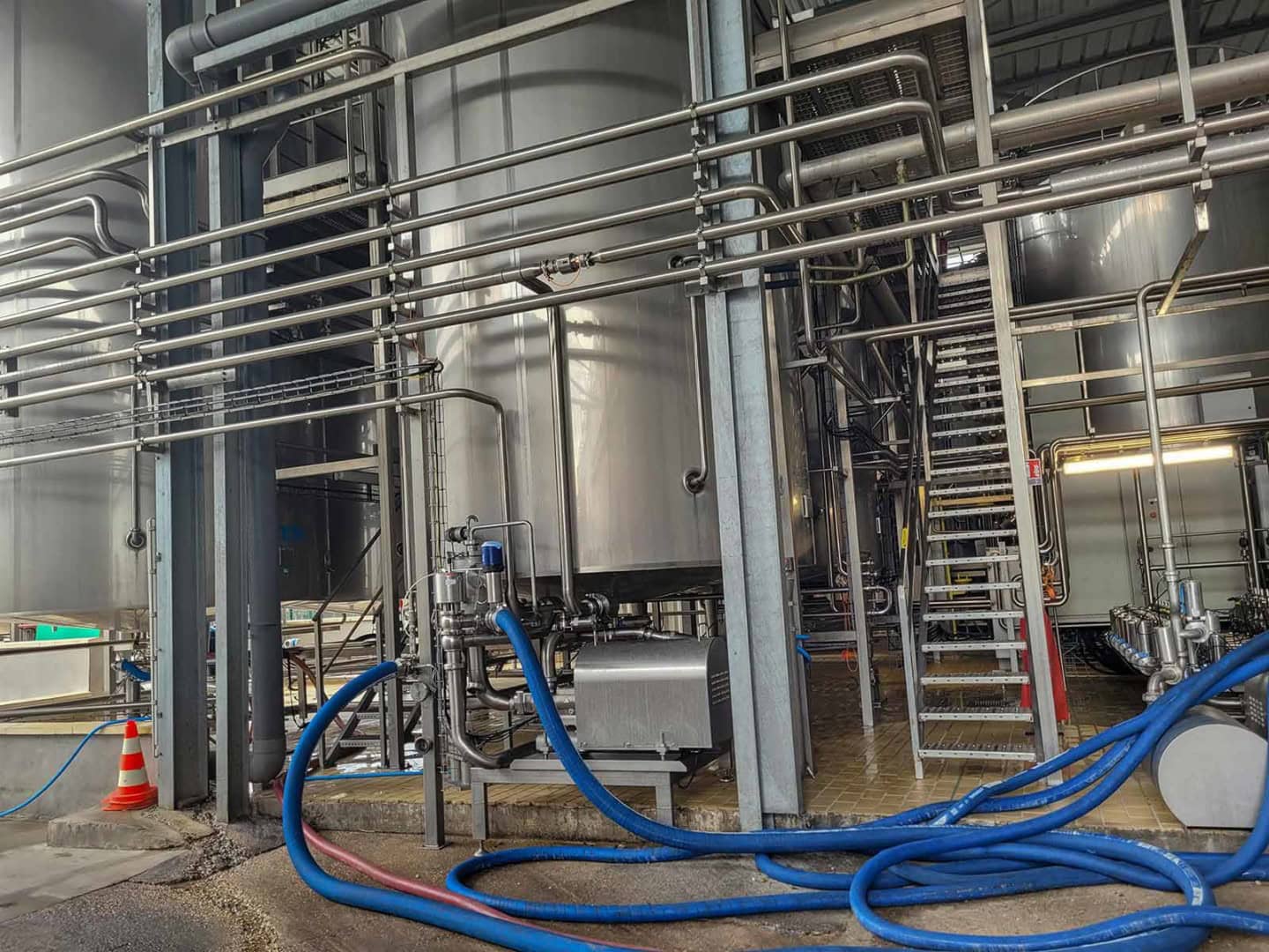
Case A – Process Vessel with Agitator: Mastering Parasitic Forces
Context: An 8,000-litre stainless-steel reaction vessel, equipped with a three-blade agitator operating at 120 rpm. Viscous fluid, process temperature at 80°C. Requirement: Continuous mass monitoring for recipe management.
Recommended Solution: 3 shear beam load cells (for natural isostatic stability), installed on stainless-steel mounting kits with high immunity to horizontal forces. Flexible couplings on all piping connected to the vessel. Transmitter featuring configurable dynamic filtering. Waterproof junction box with individual cell sensitivity adjustment (corner correction).
Key Watchpoint: Flexible couplings must be installed horizontally, aligned with the piping, to avoid introducing a parasitic vertical component. Any residual leverage or bending moment will directly affect the measurement accuracy.
Case B – Powder Storage Silo in an ATEX Zone
Context: An 80-tonne flour silo, located outdoors, supported by 4 metallic legs. ATEX Zone 21 classification (flammable dust present during normal operation). Requirement: Continuous weighing for inventory management and automated reorder triggers.
Recommended Solution: 4 ATEX II 2D certified compression load cells, installed on stainless-steel mounting kits. ATEX-compliant shielded cables. ATEX waterproof junction box with intrinsic safety barriers (Zener barriers). Transmitter located in a safe area with a galvanically isolated 4-20 mA output. Surge protection (lightning protection) on each signal line.
Key Watchpoint: Earthing (grounding) the entire installation (silo, structure, load cells, and enclosure) is a strict ATEX regulatory requirement; it must never be improvised. Ensure the earthing scheme is validated by a certified ATEX electrician.
Expert Advice
In an ATEX zone, certifying the load cell alone is not enough. The entire measurement chain (cables, junction box, and transmitter if installed within the hazardous area) must be qualified for the exact same zone and gas/dust group. A single non-compliant component invalidates the entire installation's safety certification.
Case C – High-Precision Dosing on a Small Hopper
Context: A 200 kg painted steel hopper, utilizing gravimetric dosing for a two-part epoxy resin.
Accuracy Required: ± 50 g for a 50 kg batch. Environment: Nearby conveyor vibrations, airborne dust.
Recommended Solution: 3 shear beam load cells with a 100 kg nominal capacity (providing a 100 kg safety margin, or 50% of the maximum load). Digital filtering featuring a high sampling rate (200 Hz). A transmitter equipped with a dynamic tare function and an IO-Link output for batch-by-batch traceability. Vibration isolation between the machine frame and the weighing structure.
Key Watchpoint: The display resolution must be strictly aligned with the actual system accuracy—two concepts that are too frequently confused.
Resolution ≠Accuracy : Resolution is the smallest increment that the indicator is capable of displaying (for example, displaying a weight to the nearest gram). Accuracy, however, depends on the mechanical repeatability of the installation and the precision of the system. Setting up a display to show a one-gram resolution on a structure subject to 100 g of residual vibration is a metrological illusion. You will only display unstable noise. Mechanical isolation between the machine frame and the weighing structure is the indispensable key factor required for actual accuracy to match display resolution.
Installation and Commissioning: The Field Engineer’s Checklist
A meticulous installation determines more than 50% of the long-term performance and stability of your industrial weighing system. Before powering up the system for the first time, your teams must imperatively validate these three technical pillars.
Alignment, Horizontality and Coplanarity of Supports
The most common mistake is overlooking the geometry of the mechanical supports.
Laser Alignment/Leveling: Use a laser level to verify the perfect coplanarity of the sensor mounting surfaces. If one leg is lower than the others, even by less than a millimetre, the load distribution becomes hyperstatic. A single load cell could end up supporting 80% of the silo's total weight, leading to risks of signal saturation or structural failure.
The Load Axis: Ensure that the force is perfectly centred, perpendicular, and aligned with the gravitational arrow engraved on the body of the load cell. Any residual angular or lateral force will immediately distort the measurement linearity.
Electrical Connections and Protection Against Stray Currents
Weighing sensors are sensitive electronic instruments that share their structure with heavy machinery. They must be insulated from electrical hazards.
The Electrical Shunt: Maintenance operations (such as welding) or the friction of bulk powders generate electrostatic charges and destructive stray currents. Every mounting kit must be systematically bypassed using a high-cross-section copper earth strap (bonding cable). The current will follow this path of least resistance rather than passing through the load cell's spring body and burning out the strain gauges.
Equipotential Bonding: Interconnect the lower sections of the mounting kits and wire them to the same earthing network. The power supply for the weighing indicator must be connected to a "clean" electrical network protected from industrial noise, in the exact same manner as your process PLCs.
Mechanical Decoupling and Flexible Couplings
A weighed vessel must be completely free to move along its vertical axis to transmit its entire mass to the load cells.
Orientation of Bellows/Sleeves: Install expansion joints, compensating sleeves, or flexible hoses on all incoming and outgoing piping. These flexible couplings must imperatively be positioned horizontally. If installed vertically, the mechanical resistance of the rubber or stainless steel during pressure variations will act like a spring, either supporting or pushing down on the vessel (creating a mechanical shunt effect).
The Stress Test: Manually apply a force to each sensor through the structure. The values displayed on the indicator should be similar from one support point to another. Upon releasing the force, the display must return instantaneously and strictly to zero.
Maintenance and Reliability: Do Not Let Your Measurement Chain Drift
In inventory management, a drift in the weighing chain of a vessel or silo does not just mean an incorrect line on a technical data sheet. It directly impacts your financial flows, your stock levels and the consistency of your manufacturing processes. Unlike a standard floor scale, a structural weighing system is subject to continuous mechanical and environmental stresses that inevitably alter measurement accuracy over time.
How to Detect Measurement Drift Before It Becomes a Problem
On a storage vessel or a silo weighing dozens of tonnes, identifying a loss of accuracy with the naked eye is impossible. However, several operational indicators allow you to anticipate an anomaly before it leads to critical inventory discrepancies:
Inconsistencies in Material Balancing: This is the first red flag for a stock manager. If the statistical discrepancies between your theoretical delivery notes (incoming materials) and the actual consumption of your production lines increase inexplicably, your weighing system is likely drifting.
Failure to Return to Zero After Complete Discharge: If your indicator displays a residual weight (positive or negative) when the silo or hopper is completely empty, the measurement chain has drifted. This is often caused by mechanical fatigue of the load cell's spring body or material build-up on the structure.
Divergence Between Sensors on the Same System: Vessels and silos generally rely on a multi-load cell system (3 or 4 support points). By checking the junction box, a technician can monitor the individual mV/V signal sent by each cell. This allows them to immediately pinpoint a sensor that is failing or undergoing abnormal mechanical stress.
Field Engineering: Calibration and Periodic Verification of Large Structures
While calibrating a laboratory balance is a routine procedure, calibrating a 300-tonne silo or a pressurized reactor vessel requires specific engineering methodologies. On-site, factors such as accessibility, safety, and massive material volumes necessitate verification strategies adapted to industrial realities.
Four main approaches are used to guarantee the metrological traceability of these massive structures:
The Substitution Method: The Benchmark Metrological Calibration
For large storage capacities, loading the structure solely with standard test weights is impossible. Instead, a step-by-step (staircase) procedure must be used. An initial standard load is applied based on feasibility (e.g., 5 tonnes of certified test weights), the response is recorded, and these weights are then substituted with a stable raw material. This frees up the test weights to be reused for the next step. This is the rigorous method required to map system linearity across its entire operating range.
Validation by Comparison (Weighbridge): Operational Pragmatism
In daily plant operations, a highly effective alternative method involves leveraging logistical delivery flows. After performing a zero-load tare, a bulk delivery truck—whose exact material weight has been certified before and after delivery on a calibrated weighbridge—is used. By comparing the value displayed on the silo indicator with the net delivered mass (indicated on the weight ticket), maintenance teams can validate the system's overall consistency and quickly correct any drift at a key operating point.
Flowmeter (or Volumetric) Calibration: The Process Vessel Solution
Widespread in the food and chemical sectors, this method involves injecting a volume of water into the vessel that is measured upstream by a reference mass flowmeter or electromagnetic flowmeter (which must also be certified). By adjusting the volume based on the fluid's bulk density at its specific temperature, an extremely precise calibration curve can be obtained. This is the ideal method for calibrating hard-to-reach areas or ATEX-restricted zones without handling heavy loads.
hydraulic connection captels mobile jacking unit industrial vessel on site calibration
Mechanical Verification: Hunting for Shunts Before Suspecting the Sensor
In the field, a perceived metrological drift is, in the vast majority of cases, a mechanical drift. A periodic verification campaign must always begin with a visual and mechanical inspection of the silo or vessel's surroundings. If a flexible bellows connection on a pipeline becomes fouled or rigid, or if a mounting kit stop becomes jammed, a mechanical shunt is created. This parasitic force absorbs part of the actual weight and immediately distorts the measurement, giving the false illusion of an electronic failure or sensor drift.
Expert Advice
Schedule periodic verification campaigns tailored to the criticality of your inventory and the cadence of your processes. This is the only way to guarantee the repeatability of your dosing operations, ensure structural safety, and protect the profitability of your industrial assets.
Expert Comparison Table: Which Solution for Your Application?
To dive deeper into the physics behind your measurements, explore our Comprehensive Guide to Industrial Load Cells, where we break down strain gauge operation and key selection criteria.
For a global approach to your instrumentation projects, discover our full range of solutions on our dedicated Industrial Weighing Solutions page.
Industrial Weighing FAQ: Insights from Our Experts
Why should I choose load cell weighing over a level sensor (radar, ultrasonic) for a silo?
A level sensor measures volume, which is then converted into a theoretical mass. However, bulk solids (powders, grains) form variable angle of repose cones or create "bridging" effects, while liquids shift in density as temperatures fluctuate.
In contrast, a load cell system measures the actual mass of the structure. It is the only technology completely unaffected by density variations, material characteristics, airborne dust, or surface foam.
Is it mandatory to equip every single leg of a silo with a load cell?
For liquids, it is technically possible to install fixed pivots (or dummy load cells) on some legs and live load cells on the remaining ones, as liquids naturally self-level.
However, for solids and powders, it is imperative to equip 100% of the support points. The distribution of bulk material inside a storage silo is inherently asymmetrical; any missing sensor would completely distort the calculation of the overall mass.
How does wind affect the weighing accuracy of an outdoor silo?
Wind generates both lateral and vertical forces (lift or downforce effects) that act as parasitic loads on the sensors. To counteract this phenomenon, weighing engineering utilizes mounting kits equipped with mechanical anti-tipping restraints (or stay rods). Additionally, specific digital filters are applied within the indicator to smooth the electrical signal without compromising the measurement's responsiveness.
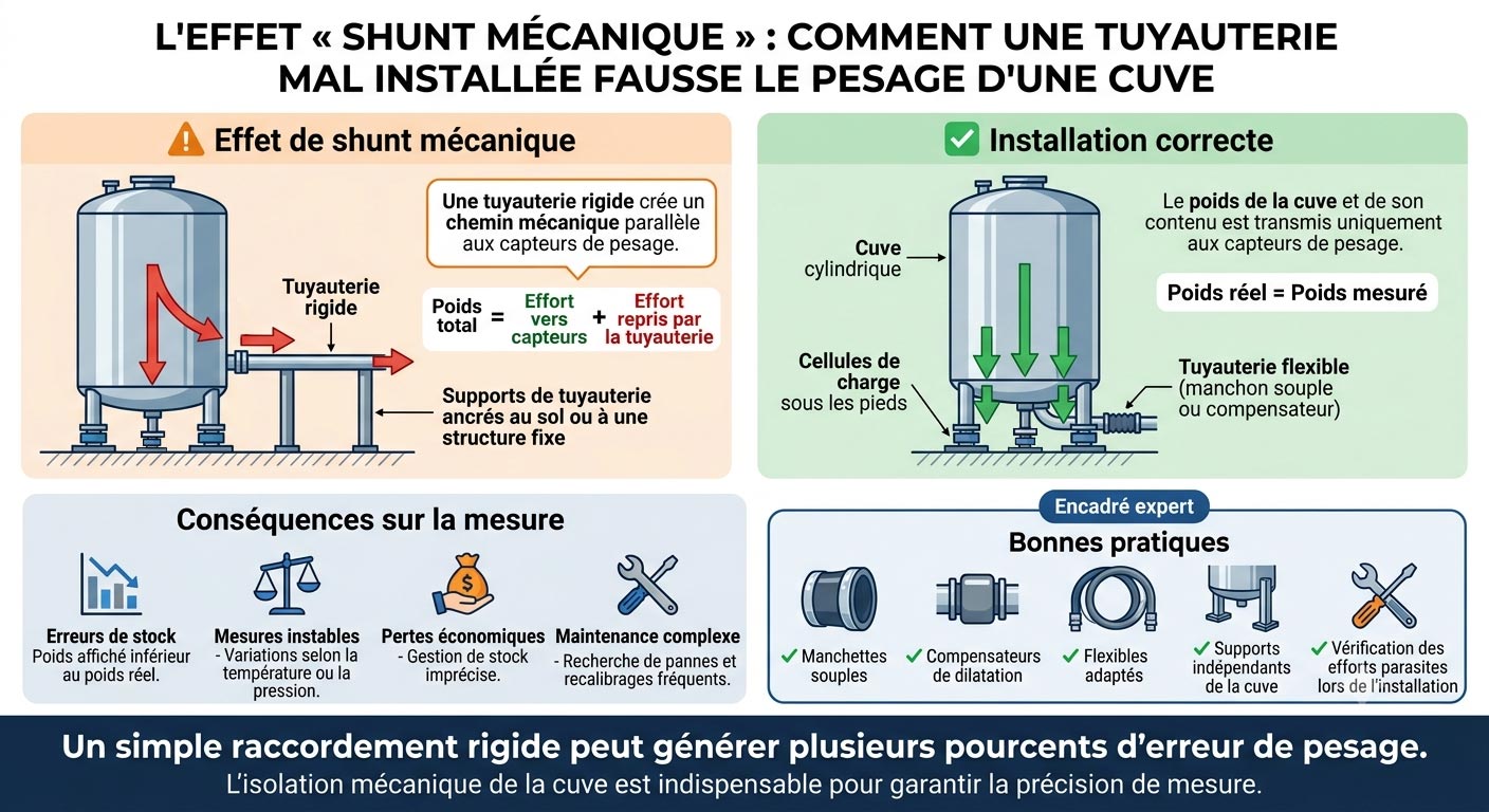
What is a "mechanical shunt" and how does it disrupt inventory management?
A mechanical shunt occurs when a rigid external component (such as a supply pipeline, electrical conduit, or maintenance walkway) is directly attached to the weighed vessel. This rigid connection "absorbs" a portion of the mechanical force that should otherwise be fully transmitted to the load cells. For the plant operator, this results in an invisible measurement drift and chronic discrepancies within inventory records.
How should piping connections be designed to avoid distorting process vessel weighing?
To mechanically isolate the vessel, all connecting flanges for fluids or solids must be flexible. This is achieved by using elastic decoupling bellows or flexible hoses installed horizontally. Additionally, the first rigid support point of the external piping must be positioned as far away from the weighed structure as possible to minimize any leverage (lever arm) effect.
What is the difference between calibration (étalonnage) and adjustment (ajustage) in an industrial weighing system?
Calibration (étalonnage) consists of comparing the values displayed by the weighing system against certified standard test weights to quantify the measurement error (without modifying it).Adjustment (ajustage) takes place afterwards; it is the technical action that modifies the weight indicator's parameters to correct this discrepancy and restore the system's operational accuracy.
How do you calibrate a high-capacity silo (e.g. 200 tonnes) without using standard test weights?
The validation by comparison method is the most practical solution in the field when physically loading standard test weights onto the structure is impossible. The procedure involves using a bulk delivery truck whose exact material weight has been certified before and after delivery on a calibrated weighbridge. By comparing the value displayed on the silo's weight indicator with the net delivered mass (printed on the weighbridge ticket), maintenance technicians can validate the system's overall consistency and quickly correct any drift at a key operating point.
What weighing accuracy can be achieved on an industrial silo?
Under optimal conditions (precise installation, recent calibration, and a stable environment), a silo weighing system can achieve an accuracy of ±0.1% to ±0.2% of full scale. For instance, this represents ±100 to 200 kg on a 100-tonne silo. In everyday industrial practice, residual error sources (such as wind loading, vibrations, and piping constraints) typically limit real-world accuracy to ±0.5%.
Is vessel weighing compatible with ATEX hazardous areas?
Yes, provided that the entire measurement chain (load cells, cables, junction box, and transmitter) is selected with the appropriate ATEX certifications for the specific zone and substance group (gas or dust). Zener barriers or galvanic isolators are mandatory to intrinsically isolate the measurement circuit from the hazardous area. Furthermore, the earthing (grounding) of the entire installation is a non-negotiable regulatory prerequisite.
How do you protect vessel load cells from stray currents during welding work?
Welding currents are a major cause of load cell destruction on industrial construction and maintenance sites. The welding current always seeks the path of least resistance to return to ground. If the ground clamp is poorly positioned, the electrical arc will flow directly through the load cell’s spring body, instantly destroying the internal strain gauges. To prevent this, every mounting kit must be equipped with a heavy-duty copper earth strap (grounding braid) that electrically shunts the sensor. Furthermore, during heavy welding or structural work, it is highly recommended to temporarily replace the live sensors with fake sensors (dummy load cells or mechanical bypasses).
What is the average lifespan of a structural weighing system, and when should it be replaced?
In a standard industrial environment—excluding aggressive chemicals or violent shock loads—hermetically sealed stainless-steel Captels load cells, combined with well-maintained mounting kits, can retain their accuracy for 15 to 20 years. Replacement should not be decided based on the equipment's age alone, but rather on specific aging indicators identified during periodic inspections. These include electrical insulation loss (often due to moisture ingress in the cable) or persistent hysteresis drift caused by structural metal fatigue of the spring body after millions of filling cycles.
Planning a Vessel, Silo, or Hopper Weighing Project?
Don't let mechanical shunts or parasitic forces ruin the accuracy of your inventory management.
Our industrial weighing experts are ready to analyze your technical and environmental constraints to engineer a solution perfectly tailored to your operational needs.
In the Industry 4.0 ecosystem, data is the engine of performance. Industrial weight measurement plays a fundamental role in numerous production and control processes. Whether dosing raw materials, monitoring filling levels, supervising automated lines, or ensuring equipment safety, the reliability of the weighing system is strategic.
At the heart of these systems lie industrial load cells, also known as weight sensors or force measurement cells. Often invisible as they are integrated into structures—under silos, tanks, or conveyors—they convert mechanical force into data usable by automation systems. Their precision, stability, and robustness directly determine the reliability of the overall system. They are the critical element of any measurement chain; an unsuitable selection can lead to metrological drift, production downtime, premature wear, or non-compliance.